|
|
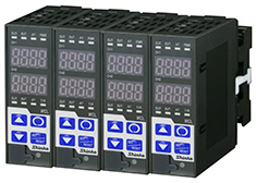
| Plug-in 2ch Digital Indicating Controller |
|
| User defined combinations |
The following can be selected.
| 2ch controller spec. |
|
PV difference input |
|
|
PV addition input |
|
|
Heating/Cooling control output |
|
|
Cascade control |
|
|
External setting input |
|
|
1-input 2-output |
|
|
Transmission output |
|
|
|
| Controller+Timer spec. |
|
Control timer |
|
|
Delay timer |
|
|
2ch, but so compact !
Economizes the control panel.
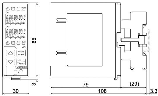
30 x 88 x 110mm (W x H x D, including the socket) |
External dimensions |
|
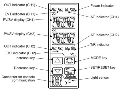
Auto-light function |
|
Display brightness is controlled after measurement from the front light sensor. This saves energy when connecting multiple units. |
|
|
|
|
Display-off function |
|
Displays are turned off when operation does not occur for the time set during Indication time setting. PV, SV or no indication is selectable during Display selection mode by keypad. |
|
|
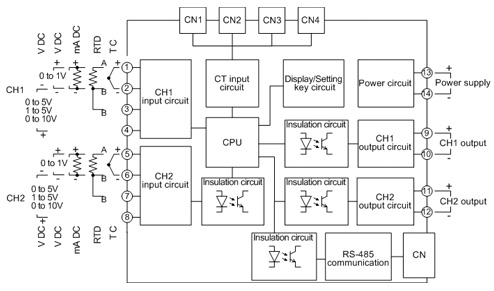
| I/O for each channel is individually selectable |
|
Input |
|
Individually selectable from thermocouple, RTD, DC current, DC voltage for each channel. Also infrared thermocouples (RD-300 series, RD-401) are usable.
(e.g.) CH1 input: Thermocouple
CH2 input: DC voltage |
|
|
|
|
Output |
|
Selectable from Relay contact, Non-contact voltage and DC current output.
(e.g.) CH1 control output: Relay contact output
CH2 control output: DC current output |
|
|
| Input sampling period selectable
|
Select from a choice of: 25ms, 125ms, 250ms via keypad.
High accuracy control can be performed by selecting optimal sampling period. |
|
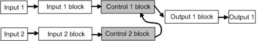
| Block function provided via console software |
Block function can be used through console software.
For each channel, Input block, Control block and Output block can be freely selected and combined.
Customizable specifications for various usages. |
| Initial selection status |
|
|
|
Input 1 block function |
|
PV difference input
[Input 1 block] receives (Input 1 - Input 2) or (Input 2 - Input 1), then outputs to [Control 1 block].
PV addition input
[Input 1 block] receives (Input 1 + Input 2), then outputs to [Control 1 block].
 |
|
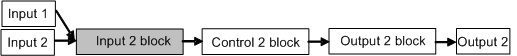
Input 2 block function |
|
PV difference input
[Input 2 block] receives (Input 1 - Input 2) or (Input 2 - Input 1) , then outputs to [Control 2 block].
PV addition input
[Input 2 block] receives (Input 1 + Input 2), then outputs to [Control 2 block].
|
|
Control 1 block, Control 2 block function |
|
Heating/Cooling control output
Heating/Cooling control computation is carried out in [Control 1 block],
then outputs from [Output 1 block] to [Output 1 (Heating)] and [Output 2 (Cooling)].
External setting input (Remote)
[Input 2] receives External input. Control computation is carried out using [Control 1 block] value received from [Input 2 block] output, then outputs from [Output 1 block] to [Output 1].
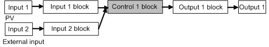
Cascade control
CH2 is a master (1st-order controller), and CH1 is a slave (2nd-order controller).
Control computation is carried out at [Control 2 block] of the master (1st-order controller). Its output will become the set value of [Control 1 block] of the slave (2nd-order controller), and control computation is carried out using this value, then outputs from [Output 1 block] to [Output 1].
|
|
Output 1 block function |
|
Output 2 output
[Output 1 block] receives [Control 1 block] output, and outputs to [Output 2].
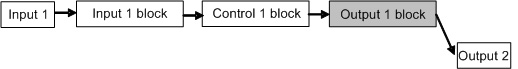
1-input, 2-outputs
[Output 1 block] receives [Control 1 block] output, and outputs to [Output1] and [Output 2].
|
|
Output 2 block function |
|
Transmission output
Selects the PV, SV or MV via Console software or keypad operation,
and outputs from [Output 2 block] to [Output 2].
 |
In addition to the above, the following functions can be used.
-Reading and setting of SV, PID and various set values.
-Reading of PV and action status
-Function change |
 |
 |
| Model |
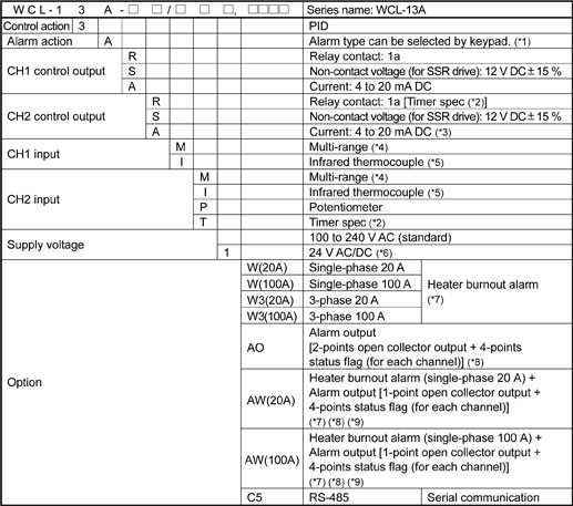
(*1) Alarm types (9 types and No alarm action) can be selected by keypad.
(*2) If Timer spec input is designated for CH2 input, CH2 output will be Timer spec output.
(*3) To use Transmission output, specify 'Current' for CH2 control output.
(*4) Thermocouple (10 types), RTD (2 types), DC current (2 types), and DC voltage (4 types) are selectable by keypad.
(*5) 8 types of Infrared thermocouple input (RD-300 series, RD-401) can be selected by keypad.
(*6) Supply voltage 100 to 240V AC is standard. When ordering 24V AC/DC, enter "1" after the input code.
(*7) Heater burnout alarm cannot be added to the Current output type.
(*8) If CH2 input is potentiometer or timer spec, this cannot be added.
(*9) Options [W], [W3], [AO], [AW] cannot be added simultaneously. |
|
|
| Rating |
| Measurement range |
Multi-range input
(*1): 50 shunt resistor (sold separately) should be connected externally. shunt resistor (sold separately) should be connected externally.
(*2): Scaling and decimal point place change are possible.
Infrared thermocouple input
| Input |
Range |
| I |
RD-300 series
or RD-401 |
-50 to 500 |
-58 to 932 |
|
| Input |
| Thermocouple |
K, J, R, S, B, E, T, N, PL-II, C(W/Re5-26)
External resistance 100 or less
(However, B input: 40 or less) |
| RTD |
Pt100, JPt100, 3-wire system
Allowable input lead wire resistance (10 or less per wire |
| Direct current |
0 to 20mA, 4 to 20mA DC
Input impedance: 50
Allowable input current: 50mA or less |
| DC voltage |
0 to 1V DC
Input impedance: 1M or more
Allowable input voltage: 5V DC or less
Allowable signal source resistance: 2k or less |
0 to 5V, 1 to 5V, 0 to 10V DC
Input impedance: 100k or more
Allowable input voltage: 15V DC or less
Allowable signal source resistance: 100 or less |
| Infrared thermocouple |
RD-300 series, RD-401 |
|
| Supply voltage |
100 to 240V AC 50/60Hz, 24V AC/DC 50/60Hz |
| Allowable fluctuation range |
85 to 264V AC, 20 to 28V AC/DC |
|
|
| General structure |
| Dimensions |
30x88x110mm (WxHxD, including the socket) |
| Mounting |
DIN rail |
| Material |
Case: Flame-resistant resin |
| Color |
Light gray |
| Front panel |
Membrane sheet
|
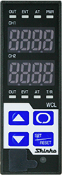
| Indication structure |
| PV/SV display |
CH1 |
7-segment Red LED display 4-digit
Character size, 10x4.6mm (HxW) |
| CH2 |
7-segment Red LED display 4-digit
Character size, 10x4.6mm (HxW) |
| Action indicators |
OUT(Green) |
Lights when control output is ON. (CH1, CH2 individually)
For DC current output type, flashes corresponding to the MV in 125ms cycles.
With Timer spec, the CH2 OUT indicator lights when timer output is ON. |
| EVT(Red) |
Lights when any alarm is ON from Alarm, Loop break alarm (LA), Heater burnout alarm (HB).
(CH1, CH2 individually) |
| AT(Yellow) |
Flashes while auto-tuning (AT) or auto-reset is performing.
(CH1, CH2 individually) |
| T/R (Yellow) |
Lights during Serial communication (TX output). |
| PWR (Yellow) |
Lights when power is turned on. |
|
|
|
| Indication performance |
| Indication accuracy |
| Thermocouple |
Within  0.2% of each input span1digit or 2 (4), whichever is greater 0.2% of each input span1digit or 2 (4), whichever is greater
R, S input: 0 to 200 (0 to 400): Within 6 (12)
B input: 0 to 300 (0 to 600): Accuracy is not guaranteed.
K, J, E, T, N input, Less than 0 (32): Within 0.4% of each input span 1digit |
| RTD |
Within 0.1% of each input span1digit, or 1 (2), whichever is greater |
DC voltage
DC current |
Within 0.2% of each input span1digit |
| Infrared thermocouple |
Within 0.2% of each input span1digit or 2 (4), whichever is greater
PV varies as infrared emissivity value is changed.
Setting range: 0.100 to 1.000 (Default value: 0.900) |
|
| Cold junction temperature compensation accuracy |
Within 1 at 0 to 50 |
| Input sampling period |
25ms, 125ms, 250ms. Selectable by keypad (Default value: 125ms) |
| Potentiometer input setting accuracy |
| Total resistance |
1k to 10k |
| Reference voltage |
1V DC |
| Accuracy |
Same as the setting accuracy |
| Temperature coefficient |
0.05%/ |
| Potentiometer input sampling |
Depends on Input sampling period selection. |
Potentiometer input high and low limit depend on the External setting input high and low limit. |
|
|
| Timer specification |
| Time accuracy |
Within 0.5% of setting time |
|
|
| Control performance |
| Setting accuracy |
Same as the indication accuracy |
| Control action |
PID control (with auto-tuning)
PI control: When derivative time is set to 0.
PD control (with auto-reset function): When integral time is set to 0
P control (with auto-reset function): When integral and derivative times are set to 0.
ON/OFF control: When the proportional band is set to 0 or 0.0.
| Proportional band (P) |
0 to 9999 (), 0.0 to 999.9 () (DC current, voltage input: 0.0 to 999.9%) |
| Integral time (I) |
0 to 3600 sec |
| Derivative time (D) |
0 to 3600 sec |
| Proportional cycle |
1 to 120 sec |
| ARW |
0 to 100% |
| Reset |
100.0 ()
(DC current, voltage input: 1000) |
| ON/OFF hysteresis |
0.1 to 100.0 ()
(DC current, voltage input: 1 to 1000) |
| Output high limit, low limit |
0 to 100%
(DC current output: -5 to 105%) |
| Output rate-of -change |
0 to 100% |
|
| Control output |
| Relay contact 1a |
Control capacity: 3A 250V AC (resistive load), 1A 250V AC (inductive load cos =0.4) =0.4)
Electrical life: 100,000 cycles |
| Non-contact voltage (for SSR drive) |
12V DC15% Max 40mA DC (short circuit protected) |
| DC current |
4 to 20mA DC, Load resistance: Max 550 |
|
|
|
| Standard functions |
| Alarm |
Alarm type can be selected by keypad
-High limit alarm
-Low limit alarm
-High/Low limits alarm
-High/Low limit range alarm
-Process high alarm
-Process low alarm
-High limit alarm with standby
-Low limit alarm with standby
-High/Low limits alarm with standby
| Setting accuracy |
Same as indication accuracy |
| Action |
ON/OFF action |
| Hysteresis |
Thermocouple, RTD input: 0.1 to 100.0 ()
DC current, voltage input: 1 to 1000 |
| Output |
No output (Read with the status flag in Serial communication.) |
| Alarm delay timer |
0 to 9999 sec |
|
| Loop break alarm |
Detects heater burnout, sensor burnout, actuator trouble.
| Loop break alarm time |
0 to 200 minute |
| Loop break alarm span |
Thermocouple, RTD input: 0 to 150 () or 0.0 to 150.0 ()
DC current, voltage input: 0 to 1500 |
| Output |
No output (Read with the status flag in Serial communication.) |
|
| SV ramp function |
When the SV is adjusted, it approaches the new SV by the preset rate-of-change (/min, /min)
When the power is turned on, the control starts from the PV and approaches the SV by the rate-of-change. |
| Auto/Manual control switching |
Auto/Manual control can be switched by keypad.
If control action is switched from automatic to manual and vice versa, balanceless-bumpless function works to prevent sudden MV change.
If control action is switched to manual, the manual MV is indicated on the display. (CHx display flashes.)
When power is turned on, control action starts from its previous controller status (last shutdown). |
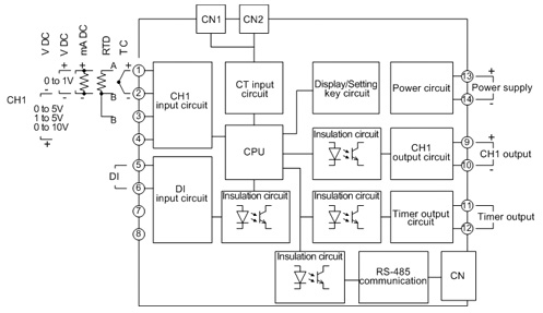
| Timer spec |
Selects either Control timer or Delay timer function.
-Control timer:
Timer starts when CH1 input exceeds Control timer start temperature.
After Control timer setting time has elapsed, control (for DC current output, output low limit) and alarm action will stop.
-Delay timer:
When DI input is ON (Closed), the timer starts.
Timer output turns ON after ON delay timer time has passed.
Timer output turns OFF after OFF delay timer time has passed. |
Cascade control
(Block function) |
To control one process, 2 inputs [CH2 as a master (1st-order controller), and CH1 as a slave (2nd-order controller)] are used for more advanced control.
MV is calculated from PV and SV of the master (CH2), and is used as SV of the slave (CH1), with which CH1 control computation is carried out, then outputs from CH1 control output.
[CH2 control output will be OFF (0mA for DC current output) or OUT2 (Cooling output) for Heating/Cooling control.]
MV (0 to 100%) of the master (CH2) corresponds to the SV (External setting low limit to External setting high limit) of the slave (CH1). |
| Heating/Cooling control output (Block function) |
This is 1ch Heating/Cooling control output spec. CH1 will be Heating output (OUT1) and CH2 will be Cooling output (OUT2), followed by control performance.
| OUT2 proportional band (P) |
0.0 to 10.0 times OUT1 proportional band
(ON/OFF control when set to 0.0.) |
| Integral time (I) |
Same as that of OUT1 |
| Derivative time (D) |
Same as that of OUT1 |
| OUT2 proportional cycle |
1 to 120sec |
| ARW |
Same as that of OUT1 |
| Overlap/Dead band |
Thermocouple, RTD input: -100.0 to 100.0 ()
DC current, voltage input: -1000 to 1000 |
| OUT2 ON/OFF hysteresis |
0.1 to 100.0 () (DC current, voltage input: 1 to 1000) |
OUT2 high limit,
OUT2 low limit |
0 to 100%
(DC current output: -5 to 105%) |
| OUT2 action mode |
Air cooling (linear characteristic), Oil cooling (1.5th power of the linear characteristic), Water cooling (2nd power of the linear characteristic) |
Output
| Relay contact 1a |
Control capacity: 3A 250V AC (resistive load)
Electrical life: 100,000 cycles |
| Non-contact voltage (for SSR drive) |
12V DC15%, Max 40mA DC (short circuit protected) |
| DC current |
4 to 20mA DC, Load resistance: Max 600 |
|
External setting input
(Block function) |
External analog signal will become the SV.
Control desired value (SV) adds remote bias value to the External setting input value.
As a setting signal, specify any DC range during input type selection via console software.
| Setting signal |
DC current: 4 to 20mA or 0 to 20mA DC
DC voltage: 1 to 5V or 0 to 1V DC |
| Allowable input |
DC current: 50mA DC or less
DC voltage (0 to 1V): 5V DC or less
DC voltage (1 to 5V): 10V DC or less |
| Input impedance |
DC current: 50 [Externally connect a shunt resistor (sold separately).]
DC voltage: 100k |
| Input sampling period |
Depends on Input sampling period selection. |
|
| Transmission output (Block function) |
Converting any value (PV, SV or MV) to analog signal every input sampling period, outputs the value in current.
To use Transmission output, specify 'Current' for CH2 control output.
| Resolution |
1/10000 |
| Current |
4 to 20mA DC (load resistance Max 550) |
| Output accuracy |
Within 0.3% of Transmission output span |
|
CH1 PV difference (CH1-CH2) input
(Block function) |
Temperature difference between CH1 and CH2 (CH1-CH2) will be the input value for CH1, and control is performed using this value.
PV = (CH1 PV - CH2 PV)
Set values such as input type, scaling and PV filter time constant can be individually set to CH1 and CH2.
However, if CH ranges differ from each other, indication and difference depend on the reference channel. |
CH1 PV addition (CH1+CH2) input
(Block function) |
Addition value of CH1 and CH2 will be the input value for CH1, and control is performed using this value.
PV = (CH1 PV + CH2 PV)
Set values such as input type, scaling and PV filter time constant can be individually set to CH1 and CH2.
However, if CH ranges differ from each other, indication and addition depend on the reference channel. |
CH2 PV difference (CH2-CH1) input
(Block function) |
Temperature difference between CH1 and CH2 (CH2-CH1) will be the input value for CH2, and control for CH2 is performed using this value.
PV = (CH2PV - CH1PV)
Set values such as input type, scaling and PV filter time constant can be individually set to CH1 and CH2.
However, if CH ranges differ from each other, indication and difference depend on the reference channel. |
CH2 PV addition (CH1+CH2) input
(Block function) |
Addition value of CH1 and CH2 will be the input value for CH2, and control is performed using this value.
PV = (CH1 PV + CH2 PV)
Set values such as input type, scaling and PV filter time constant can be individually set to CH1 and CH2.
However, if CH ranges differ from each other, indication and addition depend on the reference channel. |
| Attached functions |
Sensor correction, set value lock, automatic cold junction temperature compensation, burnout, console communication, block selection function, power failure countermeasure, self-diagnosis, warm-up indication, display-off function, auto-light function |
|
|
| Optional functions |
| Heater burnout alarm (Sensor burnout alarm included) |
Monitors heater current with CT (current transformer), and detects burnout.
This option cannot be added to DC current output type.
| Rated current |
Single-phase 20A, 3-phase 20A, Single-phase 100A, 3-phase 100A (Must be specified)
Single-phase: Detects with CT1 (CT input for CH1) and CT3 (CT input for CH2).
3-phase: Detects with CT1 & CT2 (CT input for CH1), and CT3 & CT4 (CT input for CH2). |
| Setting range |
0.0 to 20.0A (For 20A. Disabled when set to 0.0.)
0.0 to 100.0A (For 100A. Disabled when set to 0.0) |
| Setting accuracy |
5% of the rated current |
| Action point |
Set value |
| Action |
ON/OFF action |
| Output |
No output (Read with the status flag in Serial communication.) |
|
| Serial communication |
The following operations can be carried out from an external computer.
(1) Reading and setting of the SV, PID values and various set values
(2) Reading of the PV and action status
(3) Function change
| Communication line |
EIA RS-485 |
| Communication method |
Half-duplex communication |
| Synchronization method |
Start-stop synchronization |
| Communication speed |
9600, 19200, 38400bps, Selectable by keypad |
| Data bit/Parity |
Data bit: 7 or 8
Parity: Even, Odd, No parity, Selectable by keypad |
| Stop bit |
1 or 2, Selectable by keypad |
| Data format |
Communication protocol |
Shinko |
Modbus ASCII |
Modbus RTU |
| Start bit |
1 |
1 |
1 |
| Data bit |
7 |
7 or 8 |
8 |
| Parity |
Yes (Even) |
Yes (Even, Odd), No parity |
Yes (Even, Odd), No parity |
| Stop bit |
1 |
1 or 2 |
1 or 2 |
|
| Communication protocol |
Shinko protocol, Modbus (ASCII mode or RTU mode), Selectable by keypad |
|
|
|
| Insulation, dielectric strength |
| Insulation resistance |
10M or more, at 500V DC |
| Dielectric strength |
1.5kV AC for 1 minute
Between power terminal and ground
Between input terminal and ground
Between input terminal and power terminal |
|
|
| Other |
| Power consumption |
Approx. 9VA |
| Ambient temperature |
0 to 50 |
| Ambient humidity |
35 to 85%RH (Non-condensing) |
| Weight |
Approx. 200g (including the socket) |
| Accessories included |
Instruction manual, 1 copy |
Accessories
sold separately |
| Socket |
ASK-001-1 (Finger-safe, Ring terminals unusable) |
ASK-002-1 (Ring terminals usable) |
| Shunt resistor |
50 (for DC current input) |
| CT |
CTL-6S (for Heater burnout alarm 20A) (*1) |
| CTL-12-S36-10L1U (for Heater burnout alarm 100A) (*1) |
| Connector harness |
3m (for Heater burnout alarm) (*2) |
| Communication cable |
CMB-001 [For console software SWS-WCL01M)] |
(*1) For 3-phase, 2 pieces are needed for each channel.
(*2) For 3-phase, 2 lengths are needed for each channel.
|
|
|
|
|
| |
2ch controller spec
If Alarm output (AO option) is added, 4-points (CN1 to CN4) Alarm output will be used.
If the AW option [Heater Burnoout alarm (Single-phase) + Alarm output] is added, 2-points Heater Burnout alarm (CT) input and 2-points Alarm output will be used for CN1 to CN4. |
Timer spec
 |
Potentiometer input spec
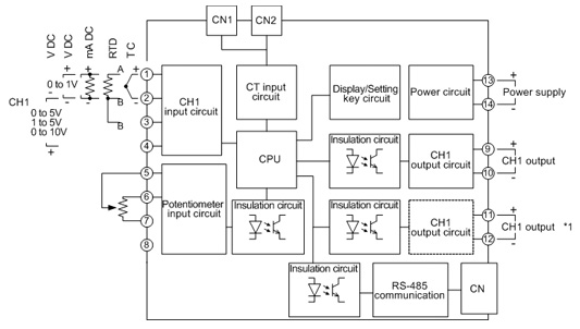
*1: Effective when Heating/Cooling control output is selected from Control 1 block or when "1-input 2-output" is selected from Output 1 block of Block function. |
|
|