|
|
|
Programmable Controller |
|
| PCA1 |
|
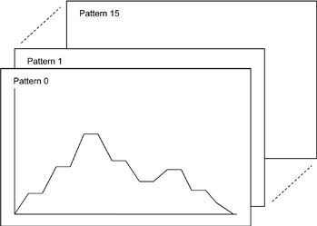
| Program capacity with 16-patterns, 16-steps
|
|
Program capacity: 16-patterns, 16-steps
Program control of up to 256 steps is possible by linking patterns. |
|
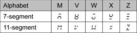
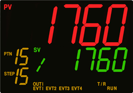
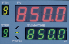
| Easily legible LCD display with 11-segment characters
|
| 11-segment character LCD display is used, so characters can be read easily. |
|
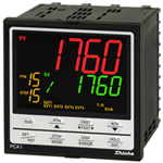
Industry-leading premium display
PV Display: 24.0 x 11.0 mm (H x W)
SV/MV/TIME Display: 14.0 x 7.0 mm (H x W) |
PCA1 and PC-900 comparison
 |
PCA1 |
 |
PC-900 |
|
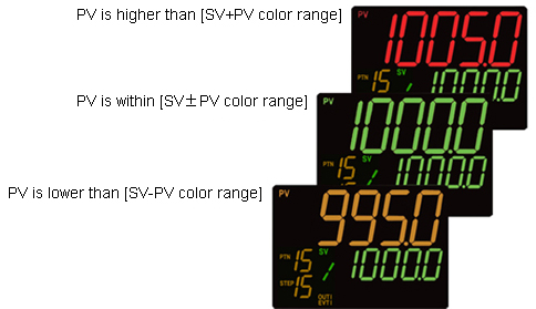
PV color changes linked with alarm
PV color changes: Orange, Green, Red, When any alarm is ON: Green --> Red, When any alarm is ON: Orange --> Red, or PV color changes by deviation between PV and SV.
Errors can be also checked via action indicators. |
 |
Backlight indication time
By setting backlight time (from no operation status until backlight is switched off), displays can be turned off, resulting in energy savings. |
|
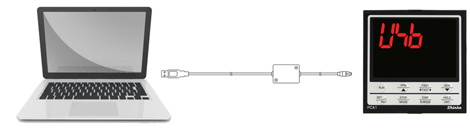
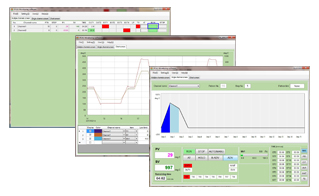
| Efficient Console software
|
Console software (SWC-PCA101M) is available for data monitoring, editing, loading, etc.
Power to the PCA1 is not required if USB communication cable (CMB-001) is used. |
|
| Easy-viewing data via Monitoring software |
| By using the Monitoring software (SWM-PCA101M), setting item change, data logging and monitoring can be carried out on a PC. |
|
| Enhanced serial communication function |
| Communication protocol: Shinko protocol, MODBUS ASCII , and MODBUS RTU
MODBUS ASCII, MODBUS RTU: A maximum of 100 pieces of multiple data Read/Write is possible. |
|
| Drip-proof/Dust-proof structure
|
| IP66 (for front panel only), usable in harsh environments where dust is present or water splashes. |
|
 |
 |
| |
|
|
|
| Input |
| Input |
| Thermocouple |
K, J, R, S, B, E, T, N, PL-II, C(W/Re5-26)
External resistance: 100  max. max.
However, B input: External resistance: 40 max. |
| RTD |
Pt100, JPt100 3-wire type
Allowable input lead wire resistance: 10 max. per wire
However, Pt100, -100.0 to 100.0 : 5 max. per wire : 5 max. per wire |
| Direct current |
0 - 20 mA DC, 4 - 20 mA DC
Input impedance: 50
Allowable input current: 100 mA max. |
| DC voltage |
0 - 10 mV DC, -10 - 10 mV DC, 0 - 50 mV DC,
0 - 100 mV DC, 0 - 1 V DC:
Input impedance: 1 M min.
Allowable input voltage: 5 V DC max.
Allowable signal source resistance: 2 k max. (0 - 1 V DC)
200 max. (0 - 100 mV DC, 0 - 50 mV DC)
40 max. (-10 - 10 mV DC)
20 max. (0 - 10 mV DC) |
0 - 5 V DC, 1 - 5 V DC, 0 - 10 V DC
Input impedance: 100 k min.
Allowable input voltage: 15 V DC max.
Allowable signal source resistance: 100 max. |
|
|
|
| Output |
| Control output |
|
Event output
EV1 - EV4 |
Relay contact
1a |
Control capacity: 3 A 250 V AC (resistive load)
1 A 250 V AC (inductive load cos =0.4) =0.4)
Electrical life: 100,000 cycles
Event output EV3, EV4 share one common terminal. |
|
|
|
| Performance |
|
| Program Performance |
| Number of patterns |
16 (Linkable) |
| Number of steps |
256 (16 steps/pattern) |
| Repetitions |
0 to 9999 times (Repetitions disabled when set to 0.) |
| Program time range |
0 to 99 hours 59 minutes/step, or 0 to 99 minutes 59 seconds/step
(When ----- is set, Fixed value control is performed using step SV.) |
| Wait value |
Thermocouple, RTD input without decimal point:
  (0 to 100) ( (0 to 100) ( ) )
Thermocouple, RTD input with decimal point:
(0.0 to 100.0) ()
DC voltage, current input:
(0 to 1000) (The placement of the decimal point follows the selection.)
(The Wait action is disabled when set to 0 or 0.0.) |
|
|
|
|
|