|
|
| Digital Indicating Controllers |
|
| BCx2 series |
|
| New standard controllers! |
BCx2 series, Shinko's digital indicating controllers are succession models of the JC series, with remarkable enhancement in operation, control performance, function, visibility, and compactness, etc.
 JCx-33A --> BCx2 Replacement JCx-33A --> BCx2 Replacement |
|
| Convenient Initial setting mode!
|
| This function can be used when usual AT cannot be performed normally due to temperature fluctuations. PID parameters can be calculated only when the temperature is rising.
|
'AT on startup' action
(1) Calculates AT (from startup, until PV is stabilized at SV)
(2) PID constants calculated
(3) Controls with PID constants set by the 'AT on startup'.
|
| Simplified Program control! |
The 9-step pattern is a standard feature.
Time signal output and Pattern end output can be selected in [Event output allocation].
-Number of patterns: 1
-Number of steps: 9
-Step SV: Scaling low limit value to Scaling high limit value
-Step time: 00:00 to 99:59 (Unit: Hours:Minutes, Minutes:Seconds)
-Wait value: 0 to Converted value of 20% of input span (or scaling span)
-Power restore action: Stop/Continue/Suspend (on hold)
-Program control start type: PV start/PVR start/SV start
-Number of repetitions: 0 to 10,000 |
Program pattern example
 |
| Simplified converter function!
|
For DC current output type, the controller can be used as a converter.
Input signal is converted to insulated 4 to 20 mA DC, and outputted at the converted value. |
|
| A variety of Event Input/Output functions! |
A maximum of 2 points of Event input (optional), and 2 points of Event output (1 point is standard).
Selectable from various Input/Output choices: Alarm output, Heater burnout alarm output (optional), Loop break alarm output, Time signal output, Pattern end output, etc. |
|
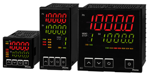
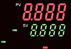
| Large, Easy-to-view, 5-digit PV, SV Displays! |
Large, easy-to-view, 5-digit PV, SV Displays, useful for indicating a wide range of measurement ranges.
-BCD2: Character size 24 x 11 mm (H x W)
-JCD-33A: Character size 18 x 8 mm (H x W) |
BCD2
JCD-33A
 |
| Compact, 60 mm-deep control panel interior! |
With a depth of only 60 mm, the BCx2 series is ideal for mounting in nearly any control panel situation.
-BCD2: Depth of control panel interior 60 mm
-JCD-33A: Needs a control panel interior of 98.5 mm |
Comparing BCD2 and JCD-33A
 |
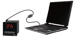
| Simple settings from a PC |
| By connecting the BCx2 to a PC using the tool cable (sold separately), and by using dedicated software, various settings can be carried out. Wiring of BCx2 is not necessary as power to the BCx2 is supplied by PC via USB. |
|
| Drip-proof/Dust-proof IP 66 |
|
IP66 structure (for the front panel) allows usage in harsh environments where the controller is exposed to water or dust. |
|
 |
 |
| Model |
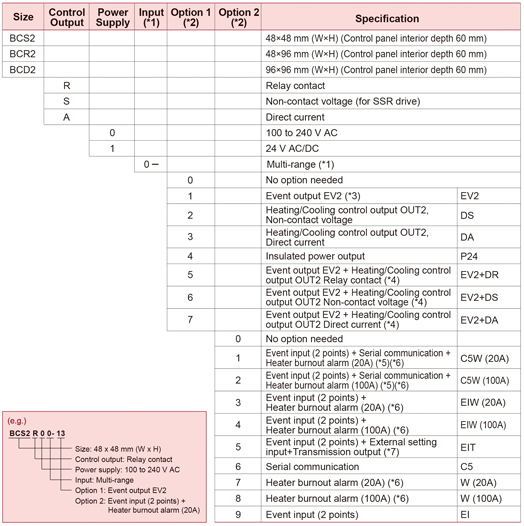
| (*1): |
Thermocouple, RTD, Direct current or DC voltage are selectable by keypad. |
| (*2): |
Only one option can be selected from Option 1 and Option 2 respectively. |
| (*3): |
Event output EV1 is standard.
The following outputs can be selected in [Event output EV1/EV2 allocation] by keypad:
Alarm output (12 alarm types and No alarm action), Heater burnout alarm output, Loop break alarm output, Time signal output, Output during AT, Pattern end output, Output by communication command, Heating/Cooling control output OUT2 (for EV2 option only)
For Event output EV1/EV2, Heater burnout alarm output and Output by communication command are available when C5W, EIW, C5 or W option is ordered. |
| (*4): |
This option can be added to the BCR2, BCD2 only. If EV2+Dx and EIT options are ordered simultaneously, Transmission output is not available since EV2 output utilizes transmission output terminals. |
| (*5): |
For the BCS2, 2 points of Event input are not available. |
| (*6): |
For Direct current output type, Heater burnout alarm does not work. CT is sold separately. |
| (*7): |
For the BCS2, 1 point of Event input is available. |
|
|
|
| Rating |
| Rated scale |
|
| Input |
| Thermocouple |
K, J, R, S, B, E, T, N, PL-II, C(W/Re5-26)
External resistance: 100  max. max.
However, for B input, External resistance: 40 max. |
| RTD |
Pt100, JPt100 3-wire type
Allowable input lead wire resistance: 10 max. per wire |
| Direct current |
0 to 20 mA DC, 4 to 20 mA DC
Input impedance: 50 max.
Allowable input current: 50 mA max. |
| DC voltage |
0 to 1 V DC
Input impedance: 1 M min.
Allowable input voltage: 5 V DC max.
Allowable signal source resistance: 2 k max. |
0 to 5 V DC, 1 to 5 V DC, 0 to 10
V DC
Input impedance: 100 k min.
Allowable input voltage: 15 V DC max.
Allowable signal source resistance: 100 max. |
|
| Power supply voltage |
100 to 240 V AC 50/60
Hz, 24 V AC/DC 50/60 Hz |
| Allowable voltage fluctuation |
85 to 264 V AC, 20 to
28 V AC/DC |
|
|
| General Structure |
External
dimensions
|
| BCS2 |
48 x 48 x 68 mm (W x H x D) (60 mm-deep
control panel interior) |
| BCR2 |
48 x 96 x 68 mm (W x H x D) (60 mm-deep
control panel interior) |
| BCD2 |
96 x 96 x 68 mm (W x H x D) (60 mm-deep
control panel interior) |
|
| Mounting |
Flush |
| Case |
Flame-resistant resin,
Black |
| Front panel |
Membrane sheet |
Drip-proof/
Dust-proof |
Front panel: IP66, Rear
case: IP20, Terminal section: IP00 |
| Display |
| BCS2 |
PV Display: 12.4 x 5.8 mm (H x W)
SV Display: 8.8 x 3.9 mm (H x W) |
| BCR2 |
PV Display: 14 x 5.8 mm (H x W)
SV Display: 14 x 5.8 mm (H x W)
STEP/MEMO Display: 14 x 5.8 mm (H x W) |
| BCD2 |
PV Display: 24 x 11 mm (H x W)
SV Display: 14 x 7 mm (H x W)
STEP/MEMO Display: 14 x 7 mm (H x W) |
|
|
|
| Indication Performance |
| Basic accuracy |
At ambient temperature
23  (for a single unit mounting) (for a single unit mounting)
|
| Effect of ambient temperature |
Within 50 ppm/ of each input span |
| Input sampling
period |
125 ms |
| Time accuracy |
Within  1.0%
of setting time 1.0%
of setting time |
|
|
| Control Performance |
| Control action |
PID control (with AT function)
PI control: When derivative time is set to 0
PD control (with auto-reset, Manual reset function): When
integral time is set to 0
P control (with auto-reset, Manual reset function): When
derivative and integral times are set to 0.
ON/OFF control: When proportional band is set to 0 (or
0.0)
| Proportional band (P) |
0 to Input span ( ) )
Direct current, voltage inputs: 0.0 to 1000.0% |
| Integral time (I) |
0 to 3600 sec |
| Derivative time (D) |
0 to 1800 sec |
Proportional cycle
|
0.5, or 1 to 120 sec |
| ARW |
0 to 100% |
| Manual reset |
Proportional
band value |
| ON/OFF hysteresis |
0.1 to 1000.0 ()
Direct current, voltage inputs: 1 to 10000 |
OUT1 high limit,
OUT1 low limit
|
0 to 100 %
Direct current output: -5 to 105% |
|
Control
output
|
| Relay contact 1a |
Control capacity: 3 A 250 V AC(resistive
load),
1 A 250 V AC(inductive load cos =0.4) =0.4)
Electrical life: 100,000 cycles
Minimum applicable load: 10 mA 5 V DC |
Non-contact voltage
(for SSR drive) |
12 V DC15
%
Max. 40 mA(short circuit protected) |
| Direct current |
4 to 20 mA DC
Load resistance: Max. 550 |
|
|
|
| Standard Functions |
| EV1 output |
The output is turned ON or OFF depending
on the conditions selected in [Event output EV1 allocation]. |
Simplified converter
function
|
This
instrument can be used as a converter for Direct current
output type.
Input signal is converted to insulated 4 to 20 mA, and
outputted. |
| Attached function |
Sensor correction coefficient, Sensor correction,
Set value lock, Auto/Manual control, SV ramp, SV Rise/Fall
rate start type, Program control, Power failure countermeasure,
Self diagnosis, Automatic cold junction temperature compensation,
Input error, Burnout, Warm-up indication |
|
|
| Optional Functions |
Event input
BCS2 (EIW, EIT, EI options)
BCR2/BCD2 (C5W, EIW, EIT, EI options) |
2 points of Event input (1 point for EIT option for
the BCS2) can be applied.
Events selected in [Event input DI1/DI2 allocation]
will be performed
depending on the DI1/DI2 input ON (Closed) or OFF (Open)
status.
Circuit current when Closed: Approx. 16 mA |
Event output
(EV2 option) |
Output will be turned ON or OFF depending on the event
conditions selected in [Event output EV2 allocation].
Relay contact 1a |
Heater burnout
alarm
(C5W, EIW, W options)
|
Monitors heater current
with CT (current transformer), and detects burnout.
EV1/EV2 output, for which Heater burnout alarm is selected
in [Event output EV1/EV2 allocation], will be turned ON
or OFF.
This alarm is also activated when indication is burnout.
| Rated current |
20 A, 100 A (Must be specified when
ordering.)
Single-phase: Detects burnout with CT1 input.
3-phase: Detects burnout with CT1 and CT2 inputs. |
| Setting accuracy |
5%
of the rated value |
|
Heating/Cooling
control
(DS, DA, EV2 options)
|
Performs Heating/Cooling
control.
One cooling method can be selected via keypad.
-Air cooling (linear characteristics)
-Oil cooling (1.5th power of the linear characteristics)
-Water cooling (2nd power of the linear characteristics)
OUT2
-DS: Non-contact voltage (for SSR drive)
-DA: Direct current
-EV2: Relay contact 1a |
Serial communication
(C5W, C5 options)
|
The following operations
can be carried out from an external computer.
(1) Reading and setting of the SV, PID values and various
set values
(2) Reading of the PV and action status
(3) Function change
| Communication line |
EIA RS-485 |
| Communication method |
Half-duplex communication |
| Communication speed |
9600, 19200, 38400bps (Selectable
by keypad) |
| Synchronization method |
Start-stop synchronization |
| Data bit/Parity |
7 bits, 8 bits/Even, Odd, No parity
(Selectable by keypad) |
| Stop bit |
1 bit, 2 bits (Selectable by keypad) |
| Communication protocol |
Shinko protocol, Modbus ASCII, Modbus
RTU (Selectable by keypad) |
Digital external setting:
Receives digital set values from Shinko programmable controllers
(PC-900, PCD-33A with SVTC option). |
External setting
input
(EIT option)
|
SV adds external analog
signal to remote bias value.
Not available for Program control.
| Setting signal |
4 to 20 mA DC |
| Allowable input |
50 mA DC max. |
| Input impedance |
50 max. |
| Input sampling period |
125 ms |
|
Transmission
output
(EIT option)
|
Converting
the value (PV, SV, MV or DV transmission) to analog signal
every 125 ms, outputs the value in current or voltage.
Outputs Transmission output low limit value if Transmission
output high
limit and low limit values are the same.
| Resolution |
12000 |
| Output |
4 to 20 mA DC (Load resistance: Maximum
550 ) |
| Output accuracy |
Within 0.3%
of Transmission output span |
|
Insulated
power output
(P24 option)
|
| Output voltage |
24 V3
V DC (when load current is 30 mA DC) |
| Ripple voltage |
Within 200 mV DC (when load current
is 30 mA DC) |
| Max. load current |
30 mA DC |
|
|
|
| Insulation, Dielectric Strength |
| Insulation resistance |
10 M minimum, at 500 V DC
When OUT1 and OUT2 are a non-contact voltage output or
Direct current output, OUT1 is not electrically insulated
from OUT2. |
| Dielectric strength |
Between input terminal and power terminal:
1.5 kV AC for 1 minute
Between output terminal and power terminal: 1.5 kV AC
for 1 minute
Between output terminal(P24) and power terminal: 500 V
AC for 1 minute |
|
|
| Other |
| Power consumption |
| 100 to 240 V AC |
Approx. 8 VA max.(When a maximum of
options are added: Approx. 11 VA max.) |
| 24 V AC |
Approx. 5 VA max.(When a maximum of
options are added: Approx. 8 VA max.) |
| 24 V DC |
Approx. 5 W max.(When a maximum of
options are added: Approx. 8 W max.) |
|
| Ambient temperature |
-10 to 55 (Non-condensing, No icing) |
| Ambient humidity |
35 to 85%RH (Non-condensing) |
| Weight |
| BCS2 |
Approx. 110 g |
| BCR2 |
Approx. 160 g |
| BCD2 |
Approx. 220 g |
|
|
|
|
|
| |
BCS2
 |
BCR2, BCD2
 |
|
| |
External dimensions (Scale: mm) |
| |
BCS2
(*) When the terminal cover is used. |
BCR2
(*) When the terminal cover is used. |
BCD2
(*) When the terminal cover is used. |
|
| |
Panel cutout (Scale: mm) |
|
BCS2
BCR2
BCD2
 |
|