|
|
| Digital Indicating Controllers |
|
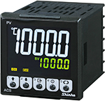
| ACS2 |
|
| Next generation controller |
The ACS2 is our flagship 48 mm square digital indicating controller, a next-generation controller with improved visibility, operability, and maintainability.
Its diverse functions optimize all types of control. It can be used for a variety of applications, including temperature control.
|
|
|
Large white LCD display provides high visibility at the work site. |
 |
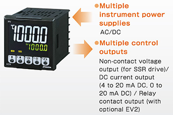
| Adopt multiple instrument power supplies and multiple control outputs
|
The use of multiple instrument power supplies and control outputs makes it easy to select the type of instrument.
It also helps to reduce the number of management man-hours and inventory
|
 |
| Adopt maintenance mode function |
Event input, event output, OUTl output, OUT2 output and transmission outputs can be output as desired. Wiring check and operation check can be performed before operation.
|
| Failure prediction maintenance is possible
|
The console software enables the user to grasp the operating status of the system.
1. Accumulated heater energizing time
2. Accumulated energizing time of the unit
3. Accumulated number of relay contact open/ close cycles
Possible to check error histories (error type, total energizing) in the past 10 times. |
|
| Easy setting with PCEasy setting with PC |
Various settings can be easily made on your desk by connecting to a PC.
[Tool cable (sold separately) and console software (free of charge) are required.] |
|
Selectable from 10 ms (DC current input, DC voltage input only), 50 ms and 125 ms.
This allows control to follow fast responses. |
The memory function allows up to 8 pairs of PID blocks to be set.
PID blocks can be switched according to the control target (process) for optimal control. |
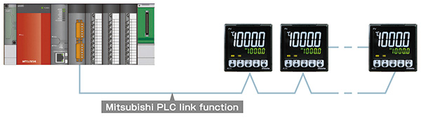
| Mitsubishi PLC link function |
Programless connection to Mitsubishi PLCs "Q series", "R series" and "F series" is possible. [A compatible IC frame AnA/ AnU common command (QR/QW)]
 |
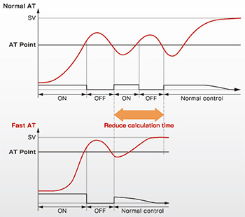
| Fast auto tuning function |
|
Compared with conventional auto tuning. the time required for PID calculation can be significantly reduced. |
 |
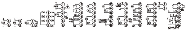
| Model |
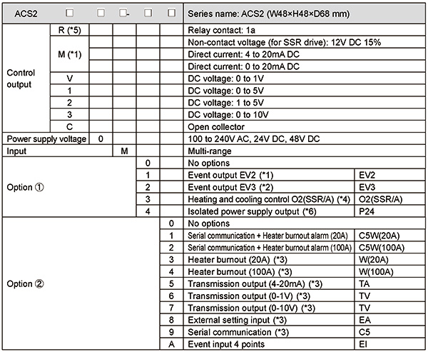
| (*1): |
When OUT1 is selected in the event output EV2 allocation selection, it becomes output multi, and SSR output, current output, and relay output can be selected. |
| (*2): |
Common of 3 event outputs is common. |
| (*3): |
For options other than C5W and EI, 2 event inputs are added simultaneously. |
| (*4): |
When 02 is selected, SSR output and current output can be selected for the cooling side output. However, the cooling output of the relay output is not available.
If you want to use the cooling output as a『elay output, select OUT2 in the event output EV2 allocation selection. |
| (*5): |
To use the heating side of the heating/cooling control with relay output, select R. |
| (*6): |
To use isolated power supply output with relay output, select R. |
|
 |
 |
| Rating |
| Rated scale |
(*1): Built-in shunt resistor
(*2): Externally mounted shunt resistor
(*3): Decimal point place change and scaling are possible.
 (Factory default: 0 to 10000) (Factory default: 0 to 10000) |
| Input |
| Thermocouple |
K, J, R, S, B, E, T, N, PL-II(ASTM E1751M-15), C(W/Re5-26)
External resistance: 100  max. max.
However, for B input, External resistance: 40 max. |
| RTD |
Pt100 3-wire type (JIS C1604-2013)
Allowable input lead wire resistance: 10 max. per wire |
| Direct current |
0 to 20 mA DC, 4 to 20 mA DC
Input impedance: 50 (receiving resistor)
Allowable input current: 50 mA DC max.
Protection circuit forward voltage: 0.9 V DC max. |
| DC voltage |
0 to 1 V DC
Input impedance: 1 M min.
Allowable input voltage: 5 V DC max.
Allowable signal source resistance: 2 k max. |
0 to 5 V DC, 1 to 5 V DC, 0 to 10 V DC
Input impedance: 100 k min.
Allowable input voltage: 15 V DC max.
Allowable signal source resistance: 100 max. |
|
| Power supply voltage |
24 V DC, 48 V DC, 100 to 240 V AC 50/60 Hz |
| Allowable voltage fluctuation |
24 V DC: 24 V ±10 %
48 V DC: 48 V ±10 %
100 to 240 V AC: 85 to 264 V AC |
|
|
| General Structure |
External
dimensions
|
48 x 48 x 68 mm (W x H x D) (Depth of control panel interior: 60 mm)
|
| Mounting |
Flush |
| Case |
Flame-resistant resin,
Black |
| Front panel |
Polycarbonate sheet |
Drip-proof/
Dust-proof |
Front panel: IP66 |
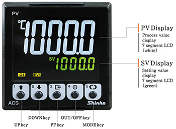
| Display |
| PV Display |
7-segment LCD display (White)
Character size: 15.2×6.0 mm (H x W)
|
| SV Display |
7-segment LCD display (Green)
Character size: 5.8×2.8 mm (H x W) |
| MEMO/STEP Display |
7-segment LCD display (Green)
Character size: 5.8×2.8mm (H x W) |
Temperature unit indicator
|
Temperature unit segment LCD display (White)
Character size: 4.0×3.4mm (H x W) |
|
|
|
| Indication Performance |
| Basic accuracy |
At ambient temperature
23  (for a single unit mounting) (for a single unit mounting)
|
| Input sampling
period |
10 ms (Direct current, DC voltage input only), 50 ms, 125 ms |
|
|
| Control Performance |
| Control action |
2 DOF PID control
Fast-PID control (PI-D control)
ON/OFF control:
Slow-PID control (I-PD control)
Gap-PID control (Gapped PID control)
| Proportional band (P) |
2 DOF PID control, Slow-PID control, Gap-PID control
Thermocouple, RTD inputs without decimal point:
1 to input span ( ) )
Thermocouple, RTD inputs with decimal point:
0.1 to input span ()
Direct current, voltage inputs:
0.1 to 1000.0 %
Fast-PID control (PI-D control)
Thermocouple, RTD inputs without decimal point:
0 to input span ()
Thermocouple, RTD inputs with decimal point:
0.0 to input span ()
Direct current, voltage inputs:
0.0 to 1000.0 % |
| Integral time (I) |
Except when Slow-PID control is selected
0 to 10000 sec or 0.0 to 1999.9 sec
When Slow-PID control is selected
1 to 10000 sec or 0.1 to 1999.9 sec
Change the setting by selecting the integral/derivative decimal point position. |
| Derivative time (D) |
0 to 10000 sec
0.0 to 1999.9 sec
Change the setting by selecting the integral/derivative decimal point position. |
OUT1 proportional cycle
|
0.1 to 120.0 sec |
| OUT1 ON/OFF hysteresis (Fast-PID control) |
0.1 to 1000.0 (0.1 to 1800.0 )
Direct current, voltage inputs:1 to 10000 |
OUT1 high limit
OUT1 low limit |
0.0 to 100.0 %
Direct current, voltage inputs: -5.0 to 105.0 %
(However, for outputs other than 4-20 mA DC or 1-5 V DC, values below 0.0% will not be output.) |
|
Control
output
|
| Relay contact 1a |
Control capacity: 3 A 250 V AC(resistive
load),
1 A 250 V AC(inductive load cos =0.4) =0.4)
Electrical life: 100,000 cycles
Minimum applicable load: 10 mA 5 V DC |
Non-contact voltage
(for SSR drive) |
12 V DC 15
% 15
%
Max. 40 mA(short circuit protected) |
| Direct current |
4 to 20 mA DC, 0 to 20 mA DC
Resolution: 12000
Load resistance: Max. 550 |
| DC voltage |
0 to 1 V DC, 0 to 5 V DC, 1 to 5 V DC, 0 to 10 V DC
Resolution: 12000
Load resistance: Min. 1 k |
| Open collector (NPN) |
Allowable load current: Max. 100 mA
Load voltage: Max. 30 V DC
Residual voltage: Max. 1.2 V DC
Leakage current when OFF: Max. 0.1 mA |
|
|
|
| Standard Functions |
| EV1 output |
The output is turned ON or OFF based on the event conditions allocated in the event output setting mode.
When “Enable” is selected for the output latch, the output remains ON even if the event condition changes from ON to OFF. |
Alarm action
|
High limit alarm, Low limit alarm, High/Low limits alarm, High/Low limits independent alarm, High/Low limit range alarm, High/Low limit range independent alarm, Process high alarm, Process low alarm, High limit with standby alarm, Low limit with standby alarm, High/Low limits with standby alarm, High/Low limits with standby independent alarm
Energized/De-energized action are applied to the above alarms, totaling 24 alarm types. No alarm action can also be selected.
Action: ON/OFF action
Output: Event output allocated to alarm output in event output setting mode
Alarm hysteresis setting: Thermocouple, RTD inputs: 0.1 to 1000.0 (0.1 to 1800.0 )
Direct current, voltage inputs: 1 to 10000
Alarm action delay timer setting: 0 to 10000 sec |
| Loop break alarm (LA) |
Loop break alarm time setting:
0 to 200 min
Loop break alarm band setting:
0 to 150 (0 to 270 ) or 0.0 to 150.0 (0.0 to 270.0 )
Direct current, voltage inputs: 0 to 1500
Loop break alarm dead band setting: 0 to 150 (0 to 270 ) or 0.0 to 150.0 (0.0 to 270.0 )
Direct current, voltage inputs: 0 to 1500 |
| Attached function |
Setting value ramp function,
Auto/Manual control selection,
Sensor correction coefficient setting,
Sensor correction setting,
Program control function,
Power failure countermeasure,
Self-diagnosis,
Automatic cold junction temperature compensation,
PV filter time constant setting
Number of moving average,
Scaling function,
Overscale,
Underscale
Sensor error,
Cold junction error,
Internal bus error,
Warm-up indication
Console communication,
Contact open/close count measurement function,
Cumulative energizing time measurement function,
Heater cumulative energization time measurement function,
Error Log,
Firmware Update Function,
Non-volatile IC memory data saving selection,
Set value lock |
|
|
| Optional Functions |
Event input
(Option: EI) |
4 points (EI1 to EI4) are added as event inputs.
For options except C5W and EI, 2 points (EI1 and EI2) are added simultaneously.
Events allocated via the event input allocation selection are executed based on whether they are in the ON (closed) or OFF (open) state.
Input points: 4 points (optional)
Input method: Contact input
Closed-circuit current: Approx. 2.3 mA
Import judgment time: 40 ms to 40 ms + within input sampling range |
Event output
(Options: EV2, EV3) |
The output is turned ON or OFF based on the event conditions allocated in the event output settings.
If “Enabled” is selected in the output latch selection, the output remains ON even when the event condition changes from ON to OFF.
For the EV3 option, the COM pin is shared. |
Heater burnout alarm
[Options: C5W (20 A),
C5W (100 A), W (20 A),
W (100A)]
|
When allocated to multiple EVT outputs, the set value is common.
When the control output is ON, if the CT input (detected current) value falls below the heater burnout alarm set value, a heater burnout error occurs and the EVT output turns ON. Additionally, the heater burnout alarm flag is set in status flag 1.
| Rated current |
20 A, 100 A (Must be specified when ordering. |
| Setting range |
0.0 to 20.0 A (If set to 0.0, it does not function.)
0.0 to 100.0A (If set to 0.0, it does not function.) |
| Setting accuracy |
5% of the rated value |
| Operation point |
Setting value |
| Operation |
ON/OFF operation |
| Output |
Event outputs allocated in the event output allocation setting will be turned ON or OFF. |
|
[Options: EV2 (Select 21 in the output allocation selection), O2 (SSR/A)]
|
Performs Heating/Cooling control.
| Cooling proportional band (Pc) |
Thermocouple input (with decimal point), RTD input:
0 to Input span ()
DC voltage, current inputs:
0.0 to 1000.0 %
When 0 or 0.0 is set:
ON-OFF control |
| Cooling integral time (Ic) |
2-DOF PID control, Fast-PID control
0 to 10000 sec
0.0 to 1999.9 sec
Slow-PID control
1 to 10000 sec
0.1 to 1999.9 sec
Change settings via the decimal point position selection.
|
| Cooling derivative time (Dc) |
0 to 10000 sec
0.0 to 1999.9 sec
Change settings via the decimal point position selection. |
| Cooling proportional cycle |
0.1 to 120.0 sec |
| Cooling output high limit, output low limit |
0.0 to 100.0 %
DC voltage, current inputs: -5.0 to 105.0 %
(However, for outputs other than 4-20mA, values below 0% are not output.) |
| Cooling ON/OFF hysteresis |
0.1 to 1000.0 (0.1 to 1800.0 )
DC voltage, current inputs: 1 to 10000 |
| Overlap/Dead band setting |
-100.0 to 100.0 (-180.0 to 180.0 )
DC voltage, current inputs: -1000 to 1000 |
| Cooling method selection |
One cooling method can be selected from Air cooling (linear characteristics), Oil cooling (1.5th power of the linear characteristics)
and Water cooling (2nd power of the linear characteristics) by key operation. |
|
External setting input
(Option: EA)
|
When Remote is selected via Remote/Local selection operation (key operation, event input), the external analog signal is used as the setpoint. The control target value is the value with the remote bias value added. However, this is disabled during program control and operates within the range from the low limit to the high limit of the external setting input.
| Setting signal |
4 to 20 mA DC |
| Allowable input |
50 mA DC |
| Input impedance |
50 |
| Input sampling period |
100 ms |
|
Transmission output
(Option: TA, TV)
|
Converting the value (PV, SV or MV transmission) to analog signal every 125 ms, outputs the value in current or voltage.
If the transmission output high limit setting and the transmission output low limit setting are the same, the transmission output low limit value shall be output.
| Resolution |
12000 |
| Output |
4 to 20 mA DC (Allowable load resistance: Maximum 550 )
0 to 1 V DC (Allowable load resistance: Minimum 1 k)
0 to 10 V DC (Allowable load resistance: Minimum 1 k) |
| Output accuracy |
Within 0.3%
of Transmission output span |
|
Insulated power output
(Option: P24)
|
| Output voltage |
24 V3
V DC (when load current is 10 mA DC) |
| Ripple voltage |
Within 200 mV DC (when load current
is 10 mA DC) |
| Max. load current |
10 mA DC |
|
Serial communication
[Options: C5, C5W (20 A), C5W (100 A)]
|
The following operations can be carried out from an external computer.
(1) Reading and setting of the SV, PID values and various set values
(2) Reading of the PV and action status
(3) Function change
| Cable length |
Max 1.2 km, Cable resistance: Within 50 (Terminators are not necessary, but if used, use 120 or more on both sides.) |
| Communication line |
EIA RS-485 |
| Communication method |
Half-duplex communication |
| Communication speed |
9600, 19200, 38400, 57600, 115200 bps (Selectable by key operation) |
| Synchronization method |
Start-stop synchronization |
| Data bit/Parity |
Data bit: 7 bits, 8 bits, (Selectable by key operation)
Parity: Even/Odd/No parity (Selectable by key operation) |
| Stop bit |
1 bit, 2 bits (Selectable by key operation) |
| Communication protocol |
Shinko protocol/MODBUS RTU/MC protocol/
SVTC (Selectable by key operation) |
| Instrument number |
0 to 95
When selecting the MC protocol, set the master to 1 and the slave to 2 to 8. |
| SV digital transmission |
Selecting SV digital transmission in the serial communication protocol selection allows digital transmission of the setpoint (SV) when combined with a digital indicating controller (with serial communication (options: C5, C5W)).
If the transmission range of the SV digital transmission sender exceeds the scaling range of the digital indicating controller, the transmission is limited to the scale range of the digital indicating controller.
Update cycle: 250 ms |
| SVTC bias setting |
ACS2 Digital external setting (active when Shinko protocol is selected)
Receives digital setpoint values from the SVTC program controller option.
The control target value is the value received via the SVTC command plus the SVTC bias value.
The control target value is the value received via the SVTC command plus the SVTC bias value, constrained within the range defined by the scaling low limit setting to scaling high limit setting.
Setting Range: Equivalent to ±20% of the input span |
| Response delay time setting |
After receiving a command from the host, the response time can be delayed.
Setting range: 0 to 1000 ms |
| PLC link function |
When MC Protocol is selected in the communication protocol selection, the PLC Link function (program-free communication function) becomes available.
This function enables serial communication connection with Mitsubishi Electric's “Q Series” PLC, allowing various data to be written to and read from PLC registers using the PLC's communication protocol.
The communication protocol uses “QW” and “QR” commands, targeting PLCs that support A-compatible 1C frame AnA/AnU common commands (QR/QW). |
| Remote output |
When selecting remote output in EVT output allocation, it becomes possible to forcibly turn the output ON/OFF from the host. |
|
|
|
| Insulation, Dielectric Strength |
| Insulation resistance |
10 M minimum, at 500 V DC |
| Dielectric strength |
Between input terminal and power terminal:
1.5 kV AC for 1 minute
Between output terminal and power terminal: 1.5 kV AC
for 1 minute |
|
|
| Other |
| Power consumption |
| 100 to 240 V AC |
Approx. 11 VA max. |
| 24 V DC |
Approx. 5 W max. |
| 48 V DC |
Approx. 5 W max. |
|
| Ambient temperature |
-10 to 55 (Non-condensing, No icing) |
| Ambient humidity |
35 to 85%RH (Non-condensing) |
| Weight |
Approx. 120 g |
|
|
|
|
| |
External dimensions (Scale: mm) |
| |
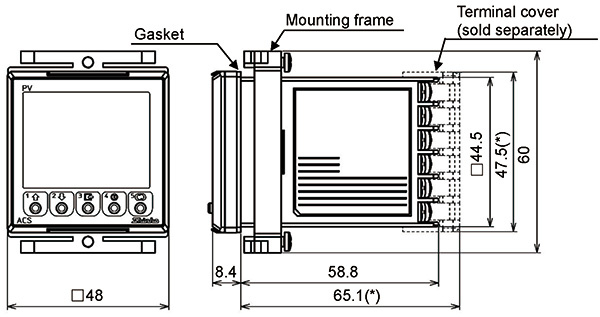
(*) When the terminal cover is used. |
|
| |
Panel cutout (Scale: mm) |
|
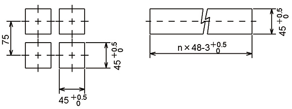
Horizontal close mounting
n: Number of units mounted
|
|